During motor operation, the ideal state is that the stator and rotor cores are axially aligned to maximize the effective iron length. However, in reality, due to the heat generated during motor operation , the components will expand. Therefore, it is necessary to determine the floating end and the stationary end according to the actual structure of the motor and leave the necessary axial clearance. In addition to normal heat deformation, misalignment of the stator and rotor cores will cause the motor rotor to move axially due to the magnetic pull during motor operation. The direct consequence of this problem is that the stator and rotor are misaligned, and axial force is generated on the bearings.
For motor products, ensuring the coaxiality of multiple cylindrical surfaces in the radial direction can meet the radial mechanical performance requirements; axial movement is prevented by controlling the magnetic centerline.
To address this issue, we introduce the concept of the magnetic centerline. The magnetic field of an electric motor is mainly manifested in the gap between the stator and rotor, called the ‘air gap magnetic field’. At a certain position, all the magnetic lines of force in the air gap magnetic field are perpendicular to the shaft, with no axial component. This position is called the magnetic centerline. Achieving a high degree of consistency between the actual magnetic lines of force in the product and the design requires good equipment and processes.
The stator windings of a three-phase induction motor are powered by a three-phase AC power supply, and the current in the rotor windings is generated by electromagnetic induction, thus converting electrical energy into mechanical energy.
When a three-phase symmetrical current is applied to the three-phase stator windings, a rotating magnetic field is generated inside the motor. The clockwise rotation of this magnetic field is equivalent to the rotor cage bars cutting the magnetic field lines counterclockwise, thus inducing an electromotive force and an induced current in the rotor cage bars. Because the rotor current is generated by induction rather than by the application of current, it is called a three-phase induction motor.
The direction of the magnetic force on the rotor cage bars can be determined using Ampere’s law. Under the action of this electromagnetic torque, the rotor will also rotate clockwise, meaning the direction of rotation of the rotor is the same as the direction of rotation of the magnetic field. The rotor speed is related to the load on the rotor shaft, but the rotor speed must always be less than the speed of the rotating magnetic field; otherwise, it will slow down due to the resistance torque caused by the lack of electromagnetic torque. Therefore, a three-phase induction motor is also called a three-phase asynchronous motor.
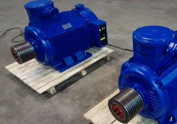
Since the rotor’s rotation direction is the same as the rotation of the rotating magnetic field, and the rotation direction of the rotating magnetic field is determined by the phase sequence of the current, swapping the two power lines will reverse the rotation of the rotating magnetic field due to the change in the current phase sequence, thus reversing the rotor’s rotation direction. Therefore, a three-phase induction motor can easily change the rotor’s rotation direction by arbitrarily swapping any two power lines.
Post time: Oct-07-2026