In automated production lines, small conveyor equipment, and packaging machinery, 220V AC geared motors are divided into two main categories: variable speed motors and fixed speed motors. Their wiring methods are completely different; incorrect wiring can lead to malfunctions such as the motor not turning, weak reverse rotation, and burnt-out controllers. This article, using actual wiring diagrams, clearly explains the standard wiring, commutation methods, and safety precautions for both types of motors.
I. Wiring Instructions for Speed-Regulating Motor (with Speed Controller)

Speed-regulating motors must be used with a dedicated speed controller, which supports stepless speed regulation and forward/reverse switching, making them the first choice when equipment needs to adjust its operating speed.
1. Power supply line (220V AC mains connection)
The green terminal block at the bottom of the controller connects to three mains power lines:
Blue wire: 220V neutral wire;
Black wire: 220V live wire;
Yellow-green bicolor wire: Protective grounding wire, must be reliably grounded to prevent leakage.
The live wire and neutral wire are not related by orientation. After connection, the power indicator light on the controller will light up, indicating that the power supply is normal.
2. Connect the motor cables.
The motor leads out a multi-colored wire harness, which is directly plugged into the upper interface of the controller through a dedicated white plug. No manual wire splitting is required, and the plug’s foolproof design prevents reverse insertion, making installation convenient.
3. Motor Reverse Adjustment Method
The motor rotates clockwise by default. To change the rotation direction, only one control wire needs to be modified:
Remove the blue jumper wire marked CCW (reverse) from the terminal and connect it to the CW (forward) terminal. Powering on the device will switch the direction of rotation. The operation is simple and requires no modification to the main circuit.
4. Speed regulation performance & optimal speed regulation range
The speed regulation range of the variable speed motor is 50Hz-90-1250rpm and 60Hz-90-1550rpm; however, the motor torque drops significantly at low speeds ≤400rpm, making it prone to overload.
Therefore, operation at excessively low speeds must be avoided. The optimal speed range for the motor is:
50Hz: 400-1250rpm
60Hz: 400-1550rpm
Advantages:
Steering adjustment without damaging the track, smooth start and stop, suitable for conveyor belts and small sorting equipment.
II. Wiring Instructions for a Constant Speed Motor (Capacitor Driven, No Speed Regulator)

Fixed-speed motors have a built-in starting capacitor, no speed adjustment function, and a fixed speed. They are simple in structure, low in cost, and are mostly used in small transmission mechanisms that do not require speed change.
The motor has three main lines A, B, and C. A capacitor is connected in parallel between lines B and C. The 220V AC mains power is connected to lines A and B to achieve forward rotation.
1. Standard forward rotation wiring
Line A: Directly connected to the mains power line;
Line B: Connect to both the neutral wire of the mains and one end of the capacitor;
C line: Connects only to the other end of the capacitor, not directly to the mains power.
2. Motor Reverse Adjustment Method
If the direction is reversed, simply change the neutral wire connection point:
The blue neutral wire of the mains power, which was originally connected to line B, was moved to line C. The original line B was left unconnected and no longer connected to the power supply. The capacitor was still connected in parallel between lines B and C. After power was applied, the motor reversed directly.
Important points to note:
The capacitor of a constant speed motor cannot be removed. Once the capacitor is disconnected, the motor will only hum when powered on and will not start. Prolonged power supply will burn out the motor windings.
III. Key Differences and Safety Standards for the Wiring of Two Types of Motors
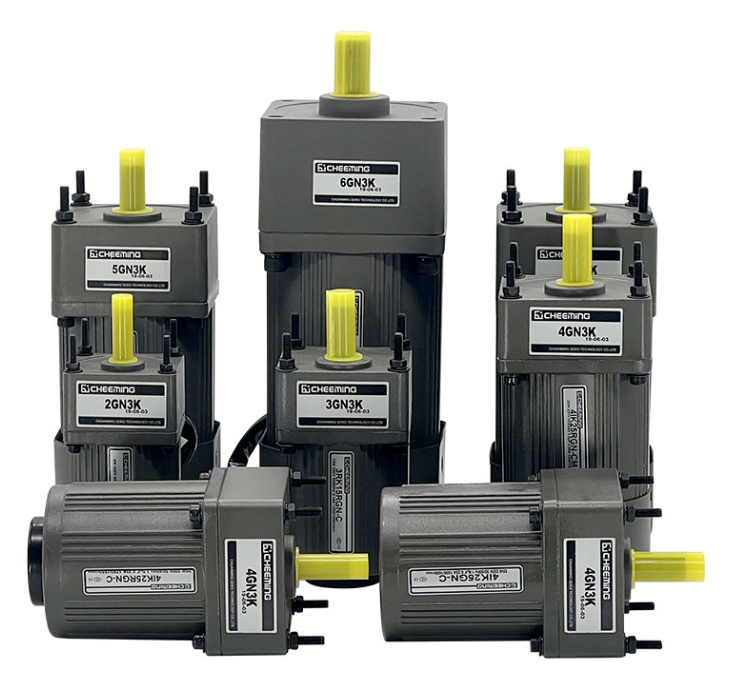
1. Comparison of core differences
Component differences: speed-regulating motors rely on speed controllers, while fixed-speed motors rely on starting capacitors;
Speed regulation capability: The speed-regulating motor can change speed steplessly, while the fixed speed motor has a fixed speed;
Reversing method: Modify the shorting wire of the controller for speed-regulating motors, and change the neutral wire terminal for constant-speed motors;
Applicable scenarios: Choose the variable speed model for frequent speed changes, and choose the constant speed model for fixed speed and low cost.
2. General Safety Operating Procedures
Before wiring, be sure to disconnect the 220V main power supply. It is strictly forbidden to plug or unplug the wiring harness or adjust the terminal wiring while the power is on.
The grounding wire must be fully connected. When working in a damp environment, the grounding wire must not be omitted to eliminate the risk of electric shock.
The copper core of the line terminal is pressed tightly to avoid loose connection and overheating, which can lead to line aging over long-term use;
After the steering adjustment is completed, first test the power-on under no-load condition to confirm that there are no abnormalities in steering and operation before working under load.
The capacitor specifications of a constant speed motor must match the motor power; do not arbitrarily replace it with a capacitor of an incompatible capacity.
IV. Quick Troubleshooting
If the motor is powered on but does not turn and only makes a humming sound: For a fixed-speed motor, check if the capacitor is broken or damaged; for a variable-speed motor, check if the motor plug is firmly inserted and if the controller power supply is normal.
The motor speed is weak: For variable speed motors, check the speed control knob parameters; for fixed speed motors, check the capacitor specifications.
Slightly electrified casing: Check if the yellow-green grounding wire is securely connected and if the grounding terminal is not loose or broken.
In summary, the wiring logic of variable speed motors and fixed speed motors is completely independent. In practice, first distinguish the type of motor, and then connect the wires step by step according to the corresponding drawings. Standardized operation can not only ensure the stable operation of the equipment, but also avoid safety hazards such as electric shock and motor burnout.
Post time: Oct-30-2026