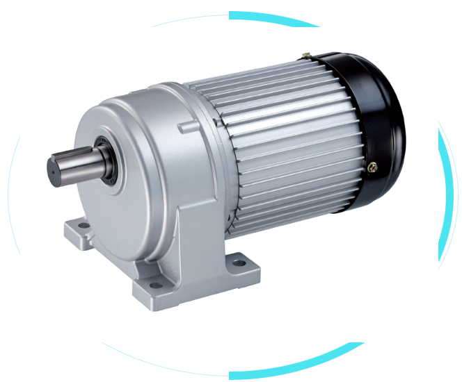
Small gear reducers are characterized by their compact structure, small size, high transmission efficiency, stable transmission ratio, reliable torque output, and relatively simple maintenance. They are suitable for low to medium power applications where installation space and transmission efficiency are limited, making them a common choice for small mechanical transmissions. Many customers encounter wiring issues during use, which are explained in detail below:
- Check the motor nameplate to determine whether it is a single-phase (220V) or three-phase (380V) motor to avoid damage to the equipment due to voltage mismatch.
- Pay attention to the motor’s rated power, current and other parameters, and match appropriate power cords and control components (such as contactors and thermal relays).
2. Prepare tools and materials
- Insulated screwdriver, wire stripper, electrical tape, power cord of appropriate specification (copper core wire, select cross-sectional area according to current), terminal block (if required).
3. Power-off operation
- Ensure the power supply is disconnected; safety first!
There are usually three interfaces: “live wire (L), neutral wire (N), and ground wire (PE)”. Some motors may have capacitor wiring (which must be connected according to the capacitor markings).
- Locate the junction box on the reducer motor, open the cover, and you will find clear terminal markings inside (such as “L”, “N”, “PE”).
- Power cord connection: Connect the live wire to “L”, the neutral wire to “N”, and the ground wire (yellow-green wire) to “PE” (grounding terminal, usually yellow-green or with a grounding symbol).
- If the motor has a capacitor, the two wires of the capacitor must be connected to the designated terminals (such as “C” and “D”) according to the instruction manual. Do not reverse them.
2. Wiring of a three-phase motor (380V)
It typically has three phase wire interfaces: “U”, “V”, and “W” and a “PE” ground wire interface.
- The terminals inside the junction box are labeled “U1, V1, W1″ (or “U, V, W”), which correspond to the three live wires of the three-phase power supply (no order requirement; if the motor reverses, any two live wires can be swapped).
- Connect the ground wire to the “PE” terminal to ensure a secure ground (to prevent leakage).
- Simple start/stop: Use a single-pole switch connected in series with the live wire (single phase) or any phase wire (three phases). One end of the switch is connected to the power supply, and the other end is connected to the corresponding terminal of the motor.
- Contactor control: Connect the main contacts of the contactor in series in the motor power supply circuit (U, V, W or L, N), connect the control coil to the control power supply (such as 220V or 380V), and control the coil to start and stop by pressing the button.
2. Wiring verification: Confirm that the live wire, neutral wire, and ground wire are connected correctly, tighten the terminal screws (to prevent loosening and overheating), and ensure there are no exposed wires.
3. Test run: Connect the power supply and jog the machine (briefly start and stop) to observe whether the reducer rotates in the correct direction (if it rotates in reverse, the phase wire can be swapped). If there is no abnormal noise or overheating, then run it normally.
- Grounding must be reliable: The ground wire cannot be omitted. It must be connected to the grounding terminal of the equipment and then connected to the earth (such as a grounding electrode) to prevent electric shock.
- Overload protection: If the motor is to be operated for a long period of time, it is recommended to connect a thermal relay in series to prevent the motor from burning out due to overload.
Post time: Jul-06-2026